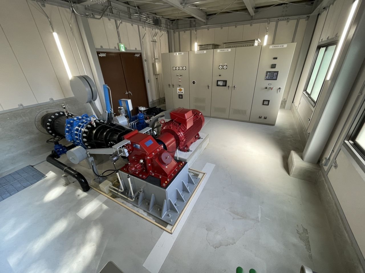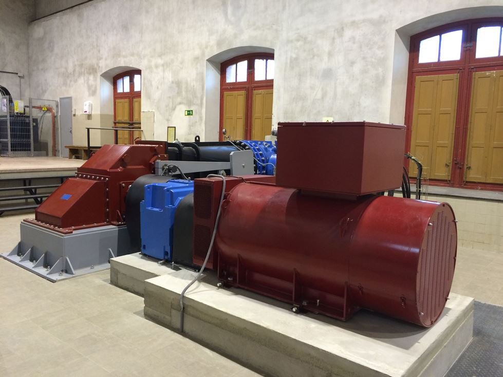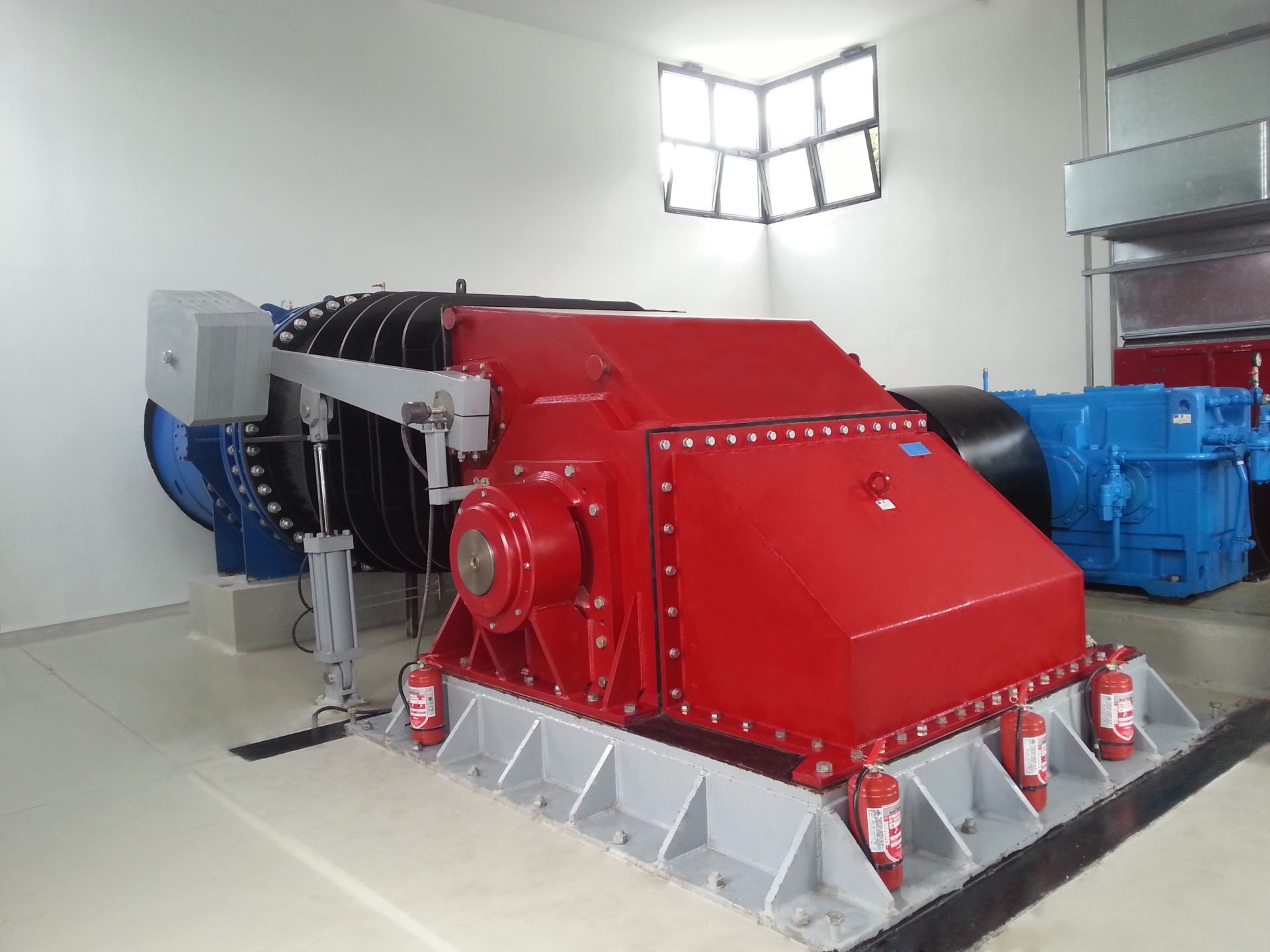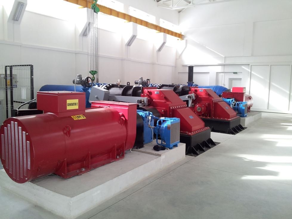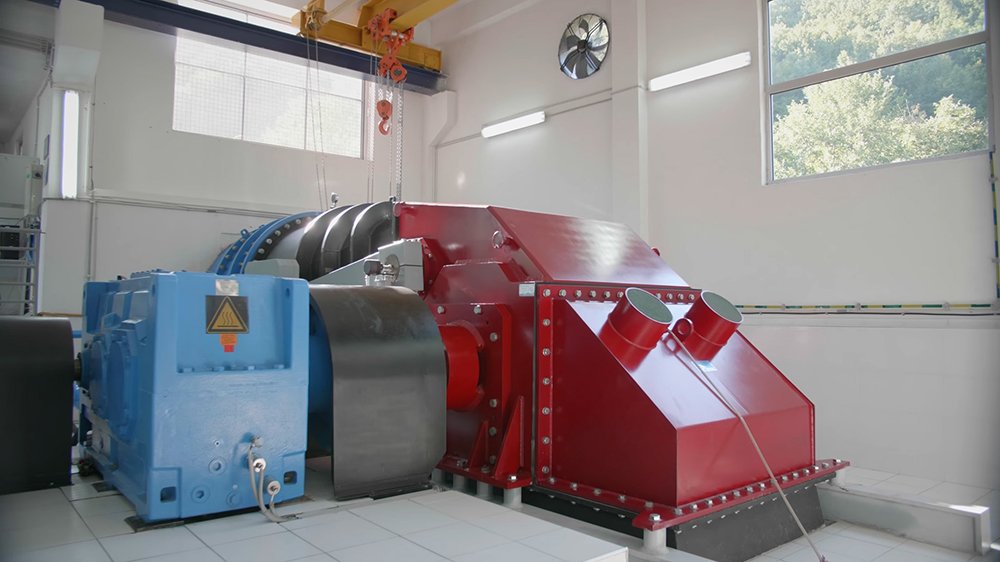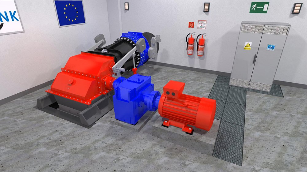
Crossflow turbines
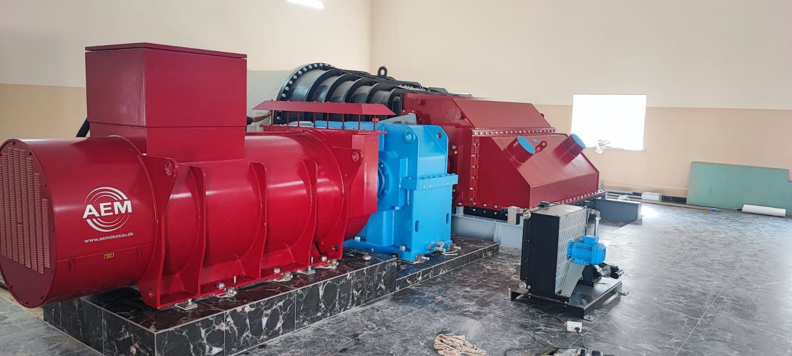
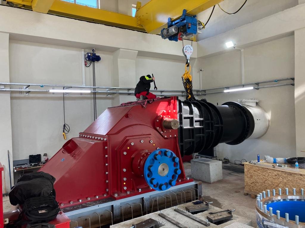
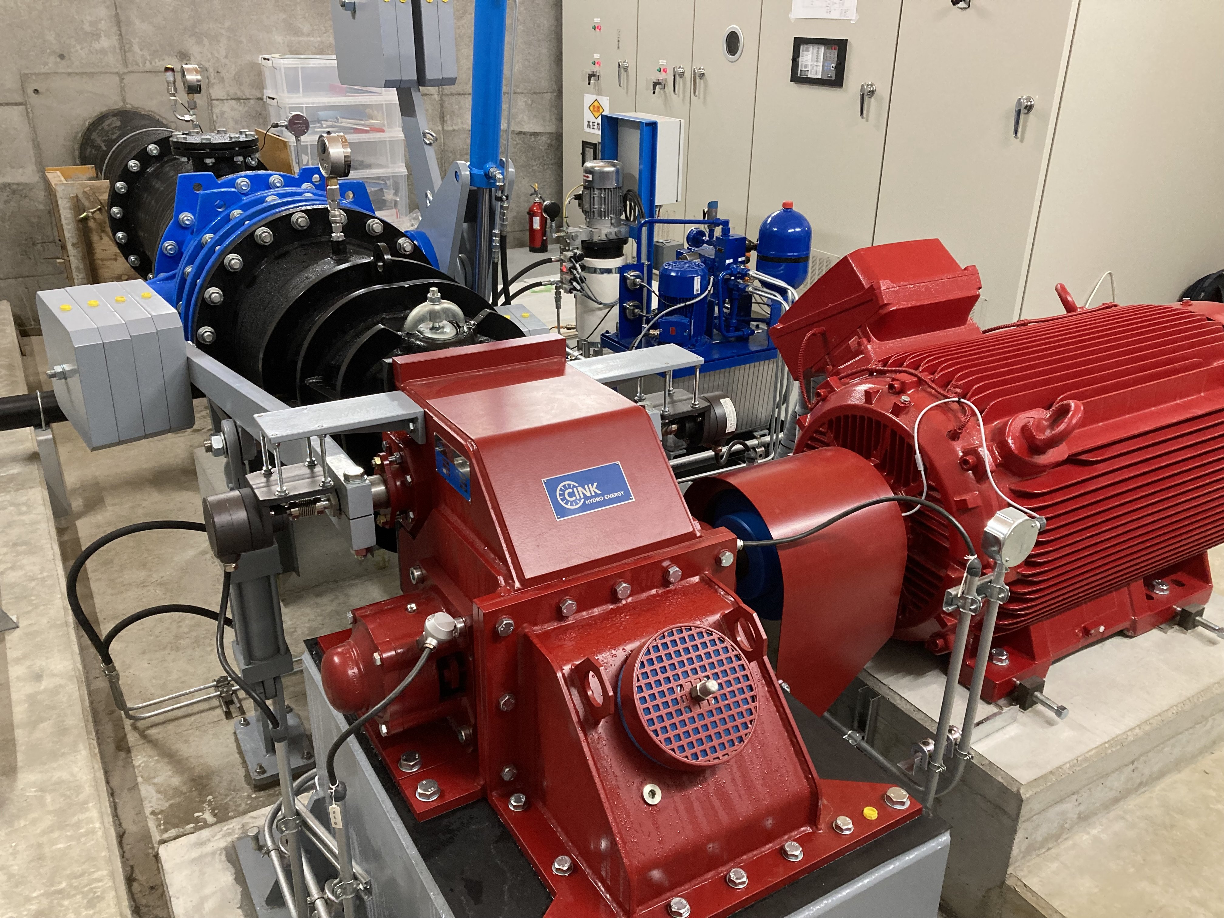
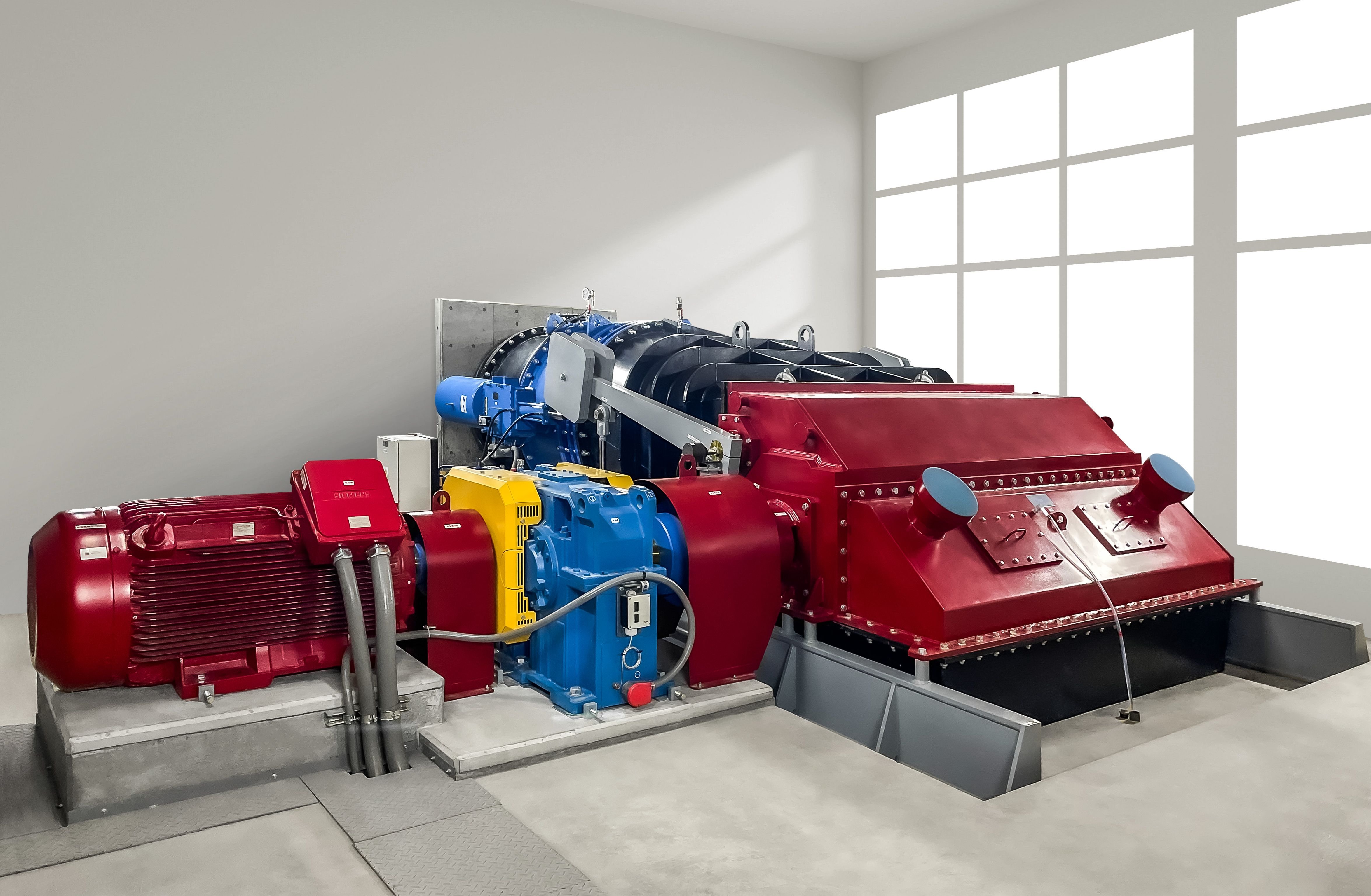
Designed according to a turbine technology from 1903 and developed for the needs of modern power plants. Tailor-made for every installation, applicable to run-of-the-river projects, dams, drinking water systems, wastewater treatment plants or to remote, isolated-operation projects. Minimal civil works, easy to install, long service life and almost maintenance-free. No complex spare parts needed.
Photogallery
Main advantages
Flexible, robust, efficient, easy to install and easy to maintain technology capable of processing even the lowest partial flows.
-
Increased annual production
Thanks to high efficiency during processing 10% to 100% of design flow and operation capability with only 6% of design flow, Crossflow turbines usually reach higher annual production. More so on rivers with varying flows.
-
Almost maintenance-free
Crossflow turbines require just occasional, regular checks in order to find out whether everything is running smoothly. Once a month, bearings should be lubricated, and once a year, a regular (8-hours) maintenance should be done according to the maintenance plan (which is of course provided by us and in the language you require).
-
Highly tolerant against foreign objects
Crossflow technology is very convenient for relatively polluted river water. Particles in the water can pass through the runner without damaging the equipment, enabling the power plant to keep running for longer time periods between the maintenance intervals.
-
Minimal civil works
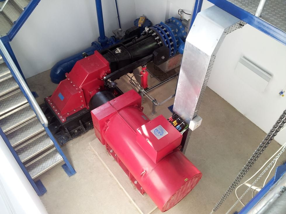
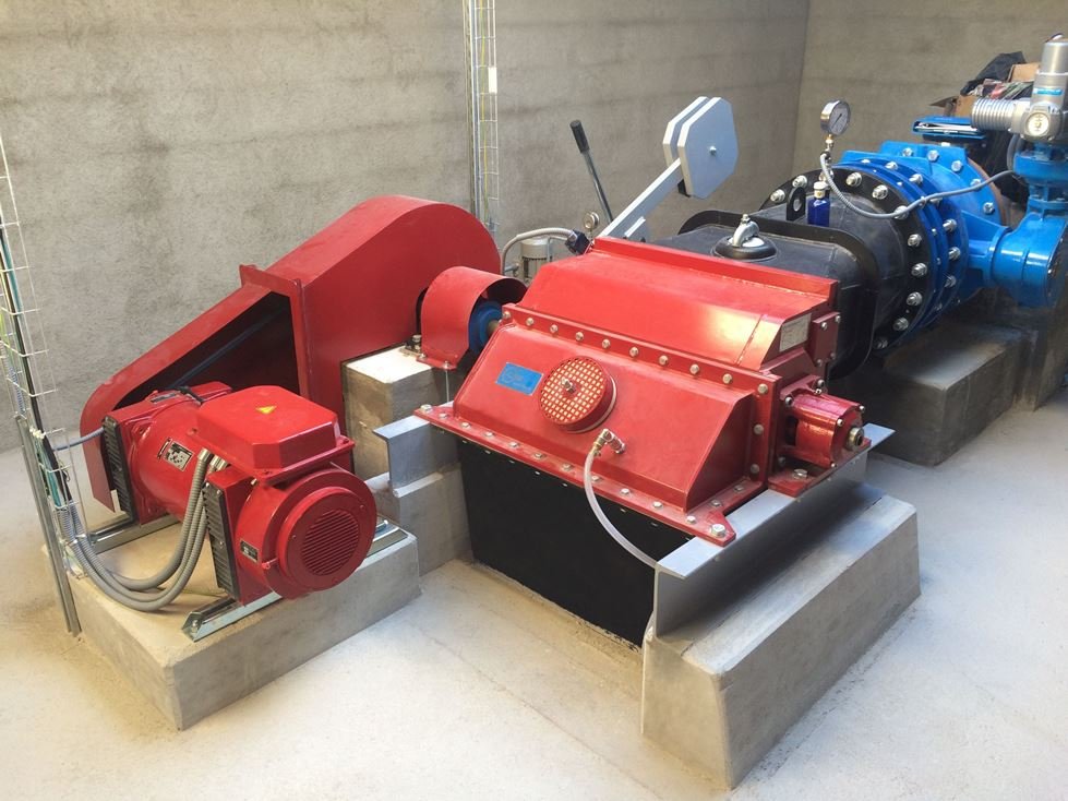
Simple power house, simple foundations and outlet channel, no need for surge tanks or surge valves etc. All that resulting in significantly lower cost of related civil works, and usually also in much faster project execution.
-
Minimal water-hammer effect
Even when there is a grid failure causing the turbine/generator to enter into the over-speed, no strong water hammer effect is caused. Just like Pelton turbine, Crossflow is an impulse-type turbine, meaning that the pressure in the penstock doesn’t rise by any significant amount (usually, the pressure increase is below 10% of the gross head). What it means is that even for a very long penstock (of several kilometres), there is no need to install any pressure relieve tanks and/or valves.
-
Non-clogging runner
Everything that comes through the trash rack and enters the penstock will also pass through the turbine and its runner without causing any problem. Obstacles with diameter of several millimetres (centimetres in case of bigger Crossflow turbines) will pass through.
-
Varying head-ready
2-cell Crossflow turbines are perfectly capable of working under constantly changing heads, delivering this way maximum performance that the project site allows and making them ideal for dam projects.
-
Simple installation
If the machine room foundations are ready and built according to our foundation plan, the installation itself can take as little as two or three days.
Operation principle
Radial, impuls-type and slightly overpressured turbine with tangential injection of the runner blades and with a horizontal shaft.
Divided inlet
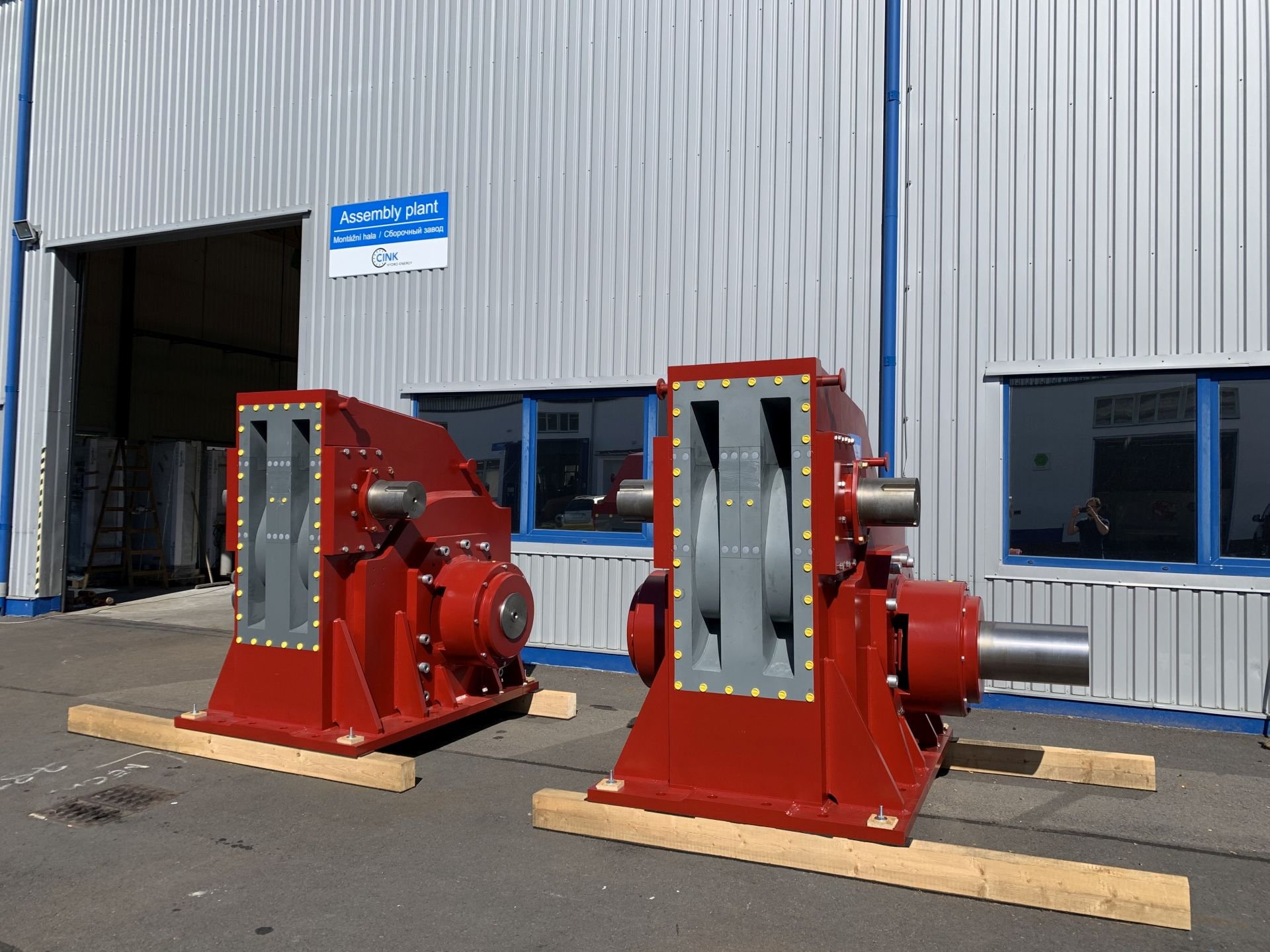
For projects with variable flow, inlet of Crossflow turbine is divided into 2 cells of equal or different sizes. That way, high efficiency across the entire flow range is secured. As a result, Crossflow turbines are able to efficiently operate with 10% to 100% of design flow and start operation with just 6% of design flow.
Self-cleaning runner
Due to its construction, the Crossflow runner is able to clean itself automatically when spinning. Any object that enters the area of runner blades is pushed out by centrifugal force with each runner spin (each revolution). The object then ends in the tail race and back in the river.
Efficiency
Low-head Crossflow turbines have the efficiency up to 84%. Bigger or higher head Crossflow turbines reach the efficiency of 87%. Thanks to the divided inlet of 2-cell Crossflow turbines, the efficiency stays almost the same across the entire operation range (from 10 to 100% of design flow).
-
Turbine casing
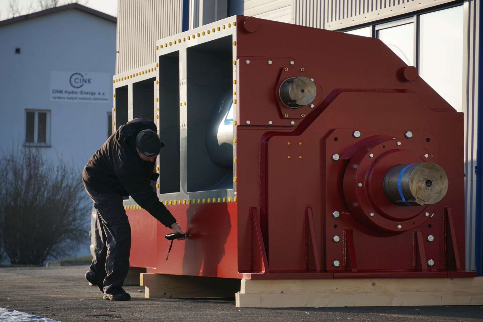
The casing of a Crossflow turbine is made of structural steel; it is robust, resistant to impacts and frost. If there is high contents of abrasive material in the water (e.g. sand, silt), the casing is made of high abrasion resistance steel. If the the actual composition of the water is considered aggressive (e.g. sea water, acidy water), all parts of the turbine in contact with water are made of suitable type of stainless steel. Inside of the turbine is then accessible by removing a simple corner casing from the top.

-
Guide vanes & Emergency shut-down weights
Crossflow turbine guide vanes serve to guiding and balancing the water from the inlet pipe to the runner. Both rotary guide vanes are set precisely in the turbine casing and can also serve as the closing device of the turbine. They are placed in highly resistant slide bearings, which do not require any maintenance. The turbine will be able to close by gravitation in the event of its shutdown, by added weights to the arms' ends.
-
Runner
Crossflow runner blades are made of polished drawn profile steel by a well-proven method. Depending on the actual hydraulic data, either structural steel or stainless steel is used for their construction. Both ends of the blades are fitted in runner discs and welded with intermediate discs to strengthen their position. Depending on the size, the runner has up to 37 blades. The linearly slanted blades create only slight axial force and therefore reinforced axial bearings with complex fitting and lubrication are not required. Runners are carefully balanced before final installation of the turbine and are subject to NDT.
-
Bearings
Crossflow turbines are equipped with self-aligning roller bearings with low rolling resistance and simple maintenance. Design of the bearing housing prevents water leakage into bearings and contact of lubricants with processed water. Furthermore, the runner is centred in the turbine casing by means of the bearings. The solution is completed with maintenance-free sealing elements. Apart from grease change once a year, the bearings do not require any maintenance.
-
Draft tube
The Crossflow turbine is, just like Pelton, an impulse-type turbine. Yet for low and medium heads, a draft tube is applied in order to utilize the entire available head. The water level inside the draft tube is controllable, though. This is ensured by a regulation air valve placed on the turbine casing, affecting the suction pressure inside the turbine. Thanks to that, turbines with suction head from 1 to 5 m can be used without any cavitation hazard.
Videogallery
Crossflow video brochure
An introduction of our most demanded product (over 300 units manufactured between 2005 and 2022). Video consists predominantly of footage from Serbian SHPP’s.
Watch videoInterview (Sutanovina)
Serbian investor, Mr. Antonijević, describing his company plants, as well as the
relationship with Cink Hydro – Energy. (G6.018/11g, H: 109 m, Q: 600 l/s, Pt: 560 kW).
2-cell Crossflow assembly
Practical animated illustration of fast and easy assembly of a Crossflow
turbine and all of its accessories to a standardly prepared power house.
